Ameba Arduino: [RTL8710AF] PWM – Let LED To Fade And Light In Turn
Materials
- Breadboard x 1
- #3 Ameba RTL8710 Board x 1
- LED x 1
- 1 KΩ Resistor
Example
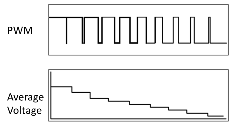
In this example, we use the PWM component to fade and light the LED in turn. A PWM component uses digital signal to simulate analog signal. By adjusting the duration of 3V3 and 0V, PWM produces the average voltage output with different value.
For example, in the figure below, as the proportion of 3v3 in a duration drops, the average voltage output decreases

Therefore, we use the varying of average voltage output of PWM to make the LED to fade and light alternately.
Open the sample code in “File” -> “Examples” -> “01. Basics” -> “Fade”:
This Arduino example uses Pin D9, however, there is no pins for D9 in RTL8710. Therefore, we modify the code to change the output pin to 13.
Please refer to the wiring diagram:

Afterwards, upload the sample code and press the reset button on Ameba RTL8710. Then you can see the LED fades and lights alternately.
Code Reference
You can find detailed information of this example in the documentation of Arduino:
https://www.arduino.cc/en/Tutorial/Fade
And the documentation of PWM on the Arduino website:
https://www.arduino.cc/en/Tutorial/PWM
In Setup, we use pinMode(pin, mode) to set D9 to output mode:
https://www.arduino.cc/en/Reference/PinMode
and use analogWrite(pin, value) to set output frequency (0~255):
https://www.arduino.cc/en/Reference/AnalogWrite
Realtek IoT/Wi-Fi MCU Solutions . All Rights Reserved. Terms of Use

